You don’t need an engineering degree to read an engineering drawing. Stick around we’re going to teach you the basics and purpose of engineering drawings. How do you read an engineering drawing?
First off, what are Engineering Drawings?
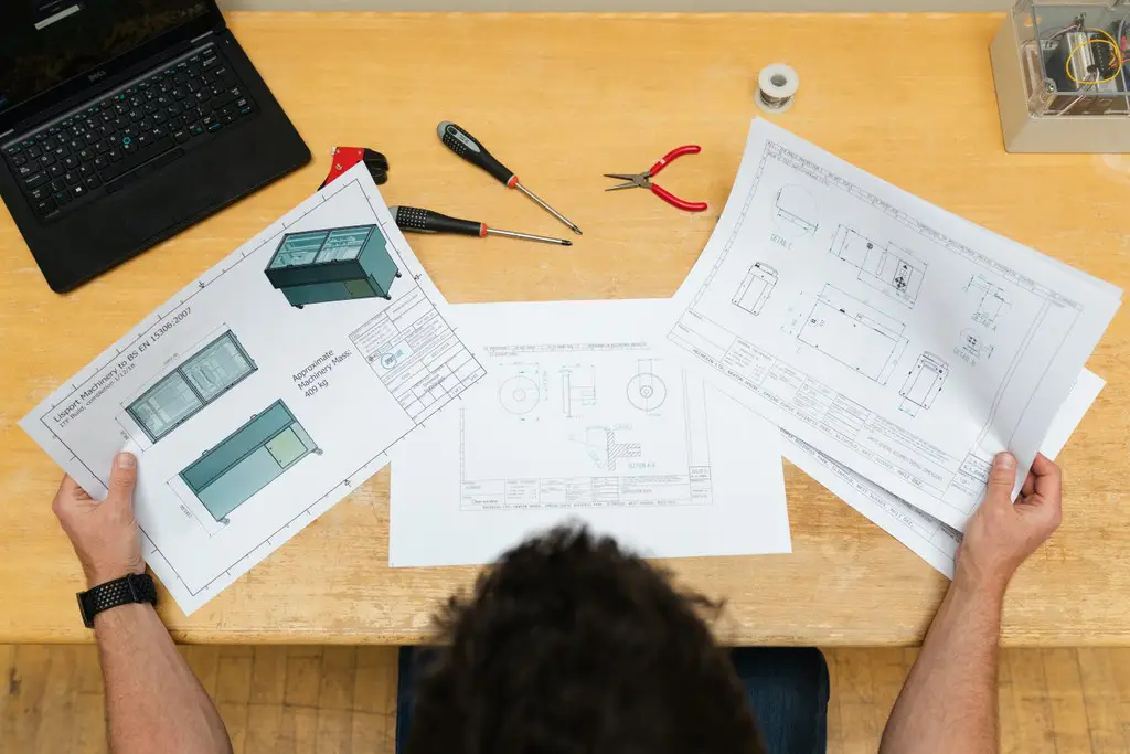
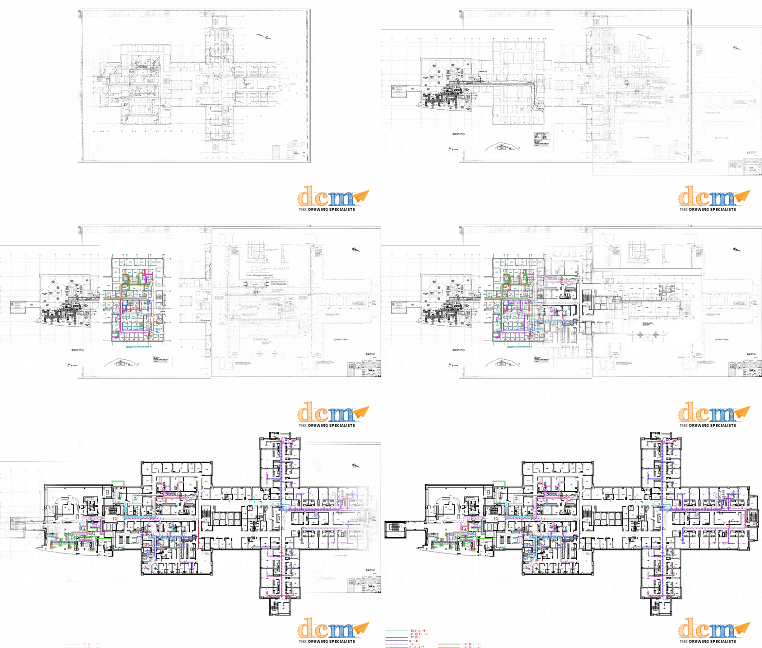
Engineering Drawings go by many names such as; Blueprints, Plans, Mechanical Drawings, A Drafting, Design Plans, Technical Drawings, etc. They can range in size and complexity, anything from; drawings for the design of a door hinge all the way to the complete Mechanical layout of a Hospital. They often contain multiple viewpoints and contain the assembly details for an object, for the sake of this article that we will assume that object is a multistory building.
What is the Purpose of Engineering Drawings?
Engineering Drawings go through a life-cycle where the purpose changes. As they transfer through these stages they often switch ownership and are used for a variety of purposes depending on the stage. Each stage is comprised of a series of revisions and approval processing before transferring to the next stage.
Design and Planning Stages – Engineers and Architects – costing, materials, structural details, project timeline and phases
Construction – These are the plans used to construct the building. Dimensions, materials, details, etc.
Operation and Maintenance – These are the plans handed over to the building owner after the building is constructed. These are used for the general function and upkeep of the building, planning for any new renovations, locations of services in the building, etc.
Next up, how do you read an Engineering Drawing?
Reading Engineering Drawings
Let’s start with the cover page. If you’re lucky enough to get your hands on an in-tact complete set that hasn’t been torn apart yet, you’ve struck gold!
The cover page ‘generally’ has a ton of valuable information that is useful when it comes to interpreting all the other drawings throughout the set – consider this your answer key when trying to decode your drawings.
A good Cover Page will include:
- Project Name and Number
- Revision Status and Date
- Drawing Index
- Key Plan
- Names & Contact Info of Consultants, Engineers, Architects, Facility Managers
- General Notes
- Legend (Symbols for Architectural, Mechanical, Electrical, Structural)
- Finish Schedules, Door Types, Wall Partition Types, etc…
Read the Title Block
Next up, we’ll share how to read the title block. The set will then be split into sections based on the different disciplines; Site, Structural, Architectural, Mechanical, Electrical. The Title Block is generally in the bottom right corner on most drawings and contains the following information;
Drawing Number – Specific to the company’s set of standards
Drawing Title – Brief, clear description of the drawing contents
Project Number – Number designation for set of drawings
Some drawings will contain a second project number or branch number for internal use, when the numbering system of the facility differs from that used by the architect/engineer.
Year – The original date the drawing was created.
- Note this does not necessarily mean this is the most current date of the drawing, a drawing will typically go through years of revisions.
Author – the creator of the drawing (will change throughout a drawing set based on the discipline)
Scale – Ratio between what is drawn and actual measurement
Checked (CHK’D) – area for initial sign off of person reviewing the drawing for accuracy
Revisions – This will often be a list with multiple entries depending on which stage the drawing is at in the project life-cycle. This shows previous changes and stages of the drawing and is listed chronologically.
Types of Drawings
Finally, the Sequence of drawings is categorized by Major Disciplines and then further divided into sub-disciplines.
Major Disciplines: Site, Structural, Architectural, Mechanical, Electrical
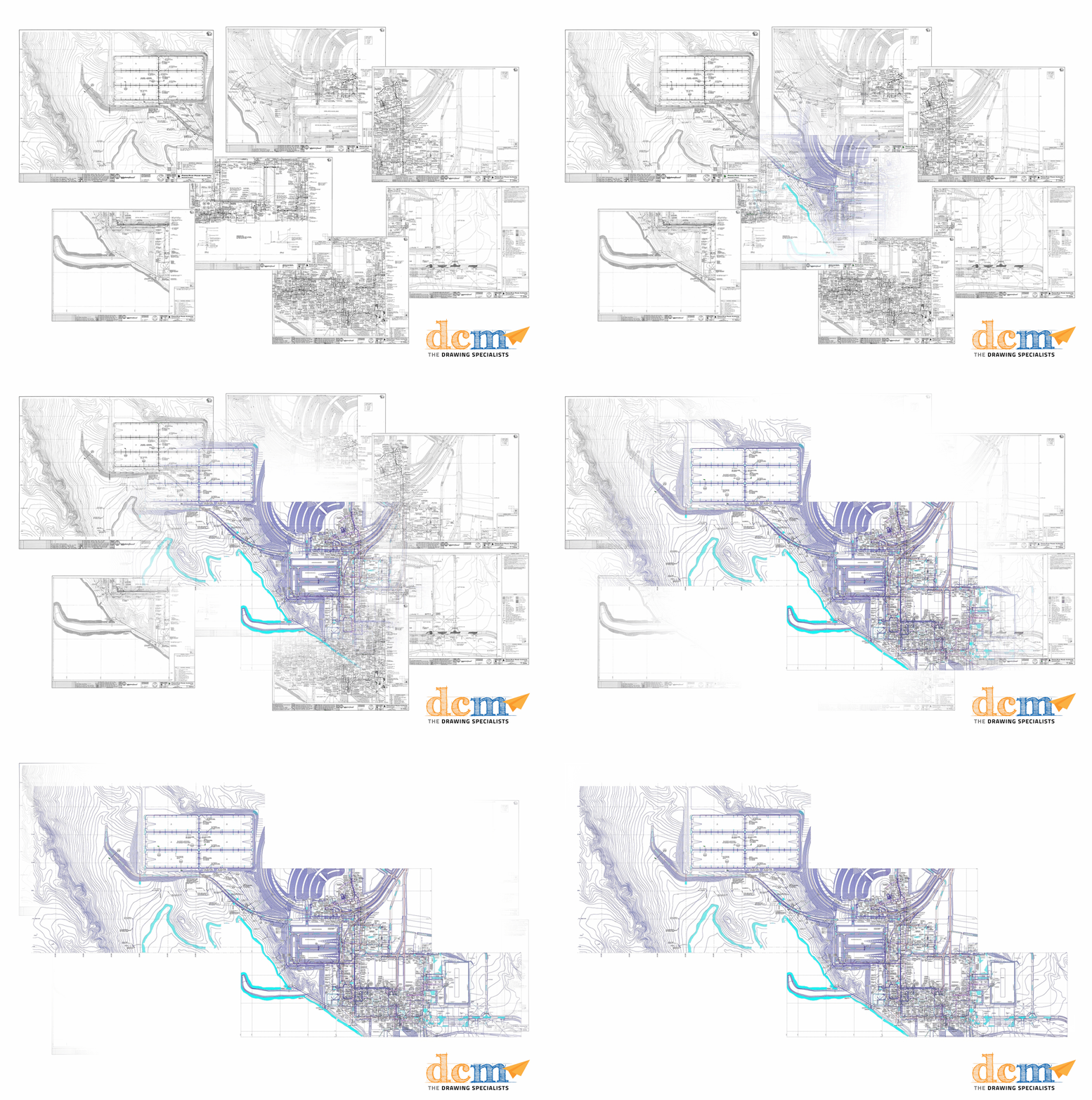
The Site Set – This will focus on the entire property that the building is located on. It will show locations of buildings, locations of mechanical and electrical services, property lines and landscaping details.
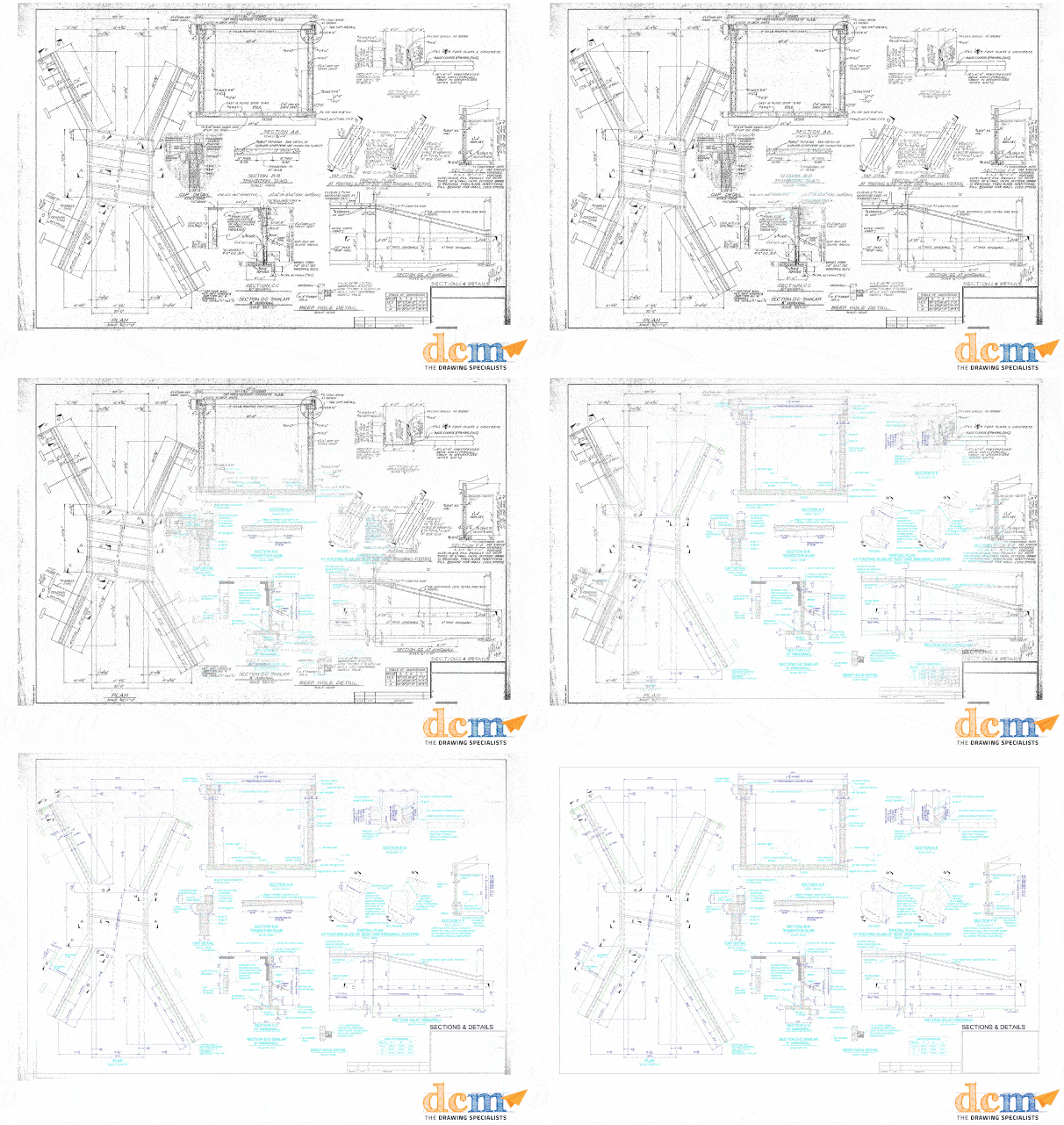
The Structural Set – is how the building is built. These primarily focus on the load-carrying components of the building. This consists of Foundation Plans, Framing, Elevations, Sections and Details.
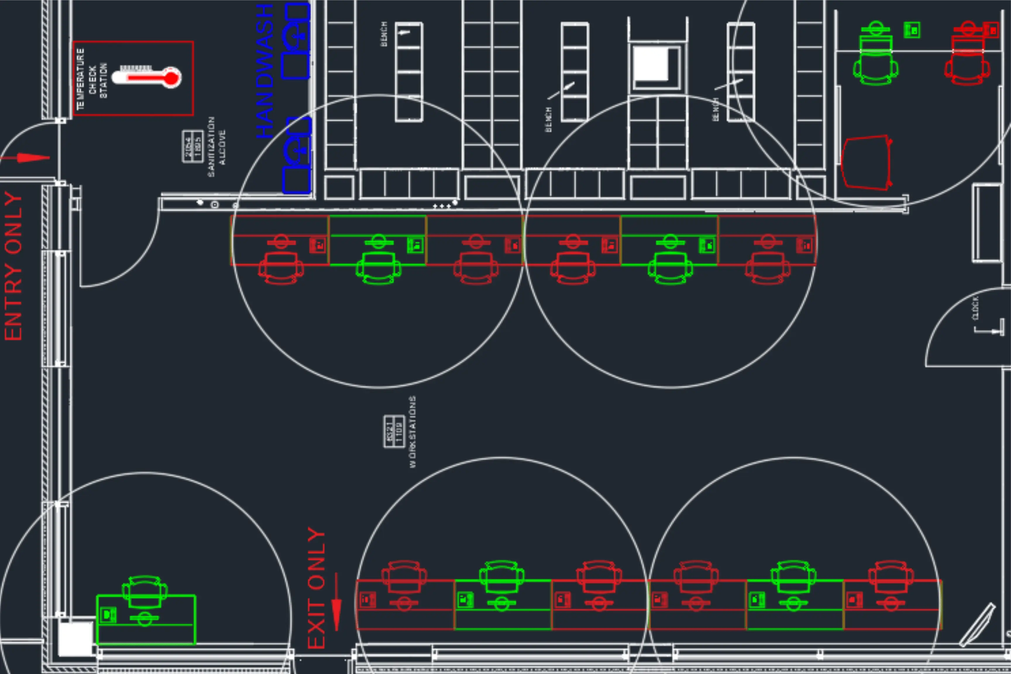
The Architectural set – is the design of the building. This focuses on the way the building appears and its layout. These include Floorplans, Millwork Details, Interior Elevations, Wall types, Sections, Reflected Ceiling Plans and so forth.
The Electrical Set – shows the layout of the electrical components throughout the building. These consist of Power layout, systems, lighting, emergency and life safety, Nurse call, Single Line Diagrams, riser diagrams, communications, Controls, Schematics, etc…
The Mechanical Set – is divided into HVAC Ventilation, Heating & Cooling Piping, Plumbing & Drainage, Medical & Laboratory Gases, Sprinklers, Riser Diagrams, etc.
In Summary
Therefore, due to the variety of purposes of engineering drawings, the level of detail and required knowledge to interpret them can vary greatly. For instance, an Electrical Engineer will have a completely different use for them compared to someone needing them for furniture layouts and space allocation. This brief summary of how do you read an Engineering Drawing was designed to be an introduction at a very top-level for anyone new to the world of engineering drawings.
To learn more about the leading drawing management company and how The Drawing Specialists can help you regain control over your engineering drawings, click here or contact us.
Your next read: How to maintain a file naming protocol?
